- 1. Introduction
- 2. Why you should learn Object-Oriented Design?
- 3. What's covered in this book ?
- 4. Prerequisites
- 5. Software Development Methodologies
- 6. The Waterfall Model
- 7. Agile
- 8. Waterfall or Agile?
- 9. Core Object-Orientation Concepts
- 10. Objects
- 11. The Class
- 12. Abstraction
- 13. Encapsulation
- 14. Inheritance
- 15. Polymorphism
- 16. Object-Oriented Analysis and Design
- 17. Collecting Requirements
- 18. Mapping Requirements to Technical Descriptions
- 19. Why do we need a Common Descriptive Language
- 20. UML Basics and fundamental diagram types
- 21. The Use-Case Diagram
- 22. Visibility
- 23. Associations
- 24. Generalization
- 25. Dependency, Aggregation, composition & Realization
- 26. Sequence Diagrams
- 27. Activity Diagrams
- 28. Statechart diagrams
- 29. Case Study: Designing a Note-Taking App
- 30. Collecting the requirements
- 31. Creating User Stories
- 32. Diagraming the Main Use Cases
- 33. Identifying the classes
- 34. Describing the Flow of Note Creating using Sequence Diagrams
- 35. The Note Object´s StateChart Diagram
- 36. What is next?
- Summary of the relationships and their graphical representation
1. Introduction
This notes will teach you fundamental knowledge needed to design and build object-oriented software systems.
- Learn basic syntax.
- Design a software system by applying common object-oriented programming principles.
- Learn how to describe our design so that others can understand it clearly.
- Learn how to answer object-oriented related questions during job interviews.
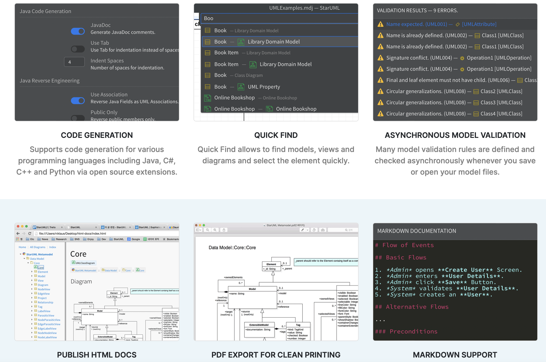
This book is about object-oriented software design related concepts and the Unified Modeling Language
UML: Provides a standard set of visual symbols and diagramming techniques used to effectively communicate software design concepts. Using UML you can sketch our systems easily.
The steps required to create a software system are not carved in stone, this is known as Software development methodlogies. We are going to discuss two widespread methodologies in this book.
Object-orientation has been around since the 80´s, but its principles are still valid and used in modern software design. I dedicated an entire section to the fundamental object-orientation concepts.
Next, you will learn about the various steps of the object-oriented software analysis and design process. Mastering these techniiques will let you design your software systems more efficiently.
The, we will dive into UML. I will talk about the core UMRL notions and the fundamental diagram types.
I am going to talk about use cases, the primary way of describing the requirements in a formal way.
I will introduce you the class diagrams, which let us describe the main types that form a system and the relationships between them.
We will then talk about sequence diagrams, which are the way to go if you want to represent the dynamic behavior of your objects. We will also have a look at the activity and the state diagram.
After discussing the most important UML diagram types, we will solidify the concepts you learn. I am going to walk you through the steps of designing a note taking application from scratch.
We will start by collecting the requirements. Then, we will create the use case diagrams. After identifying the players, we will model the classes and their relationships. You are going to also see the sequence and the state diagram in action.
- The waterfall model, which requires you to have a detailed plan before starting any coding. The requirements need to be fixed, so no changes are expected during development.
- The change friendly, responsive Agile Approach, which works great for projects where the expectations can change rapidly and frequently.
Both help us to design, coding, product management, budgeting, testing, documentation, release and maintenance.
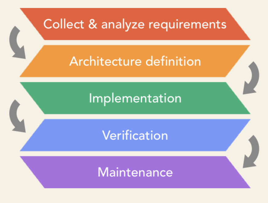
The Waterfall is a linear model. It defines development steps or phases. You start executing one step, complete it and then start the next one. This approach gives us a steady, downward order. Hence the name Waterfall.
The development process flows in cascades. Each development phase requisites the previous one to be completed. Let's talk a bit about these phases.
- First, we collect and analize the requirements.
- After collecting and analyzing the requirements, we define the overall design of our software. The design should be as clear and detailed as possible.
Questions to ask:
- Which packages or components will form our system?.
- What are the fundamental types of each component?.
- How do these types interact with each other to achive the required functionality?.
- Is our software secure?. How about performance?.
- How does our software respond to errors?. How do we handle edge cases?.
- Should we extend our system in the future?.
- Which third-party components do we use?.
- The software development phase is usually divided into smaller units. Each unit is then implemented and tested by developers.
- Verification phase.
- Test are executed to ensure that the software works as expected.
- Maintenance phase.
- The waterfall model is used for life-control, medical and military systems.
- The waterfall is a perfect choice if all requirements are precisely defined and will not change over time.
- If the client changes their mind frequently, or our design misses essential aspects, we are going to hit problems during development or testing. In such cases, we should follow a different approach.
7. Agile
Agile is a relatively new approach to software project management. It all began with the agile manifesto in 2001. This manifesto was an attempt to end the proliferation of methodologies that had develped.
The agile manifesto defines four values:
- Individuals and interactions over the processes and tools.
- Working software over comprehensive documentation.
- Customer collaboration over contract negotiation.
- Responding to change over following a plan.
Agile welcomes changes even at the later phases of the development cycle.
Some planning is also required for agile projects. But we don't try to come up with a detailed plan for the entire project before starting any development activities.
As a consequence we are not blocked until all the requirements are clarified and each and every question gets answered.
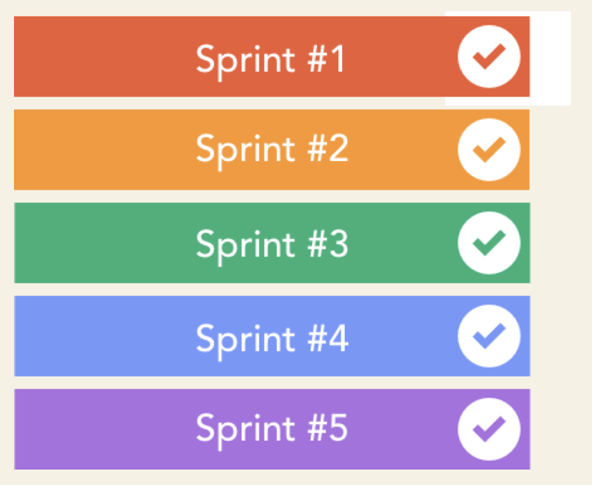
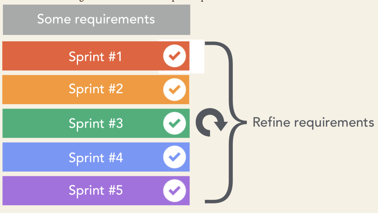
The main idea behind Agile is that we can provide functional software iteratively instead of delivering the entire project all at once. The work is broken up into shorter chunks called sprints.
The Sprint is usually two to four weeks long. At the end of each sprint the team should deliver a version that is an improvement over the previous sprint's outcome.
This interactive approach provides an opportunity to frequently review the product that is being developed. Stakeholders have a chance to evaluate the software and provide their feedback early on rather than waiting for the final product to be delivered. These frequent checkpoints are super useful as they ensure that the project evolves in the right direction.
Unlike the waterfall, agile methodlogies do not separate testing from development. Testing is tightly integrated with development and the entire team owns the responsibility for the quality of the product. Also involving the bussiness users in the development process stands at the core of agile approaches.
There is a strong relationship between the project team and the stakeholders and bussiness users. This model works best in situations where the requirements can't be defined up-front.
Agile is a good fit for the software projects that are depending on many uncertain factors and changes are to be expected.
One of the big benefits of this collaborative model is that it usually leads to higher customer satisfaction. Also team memembers will likely be more motivated by engaging customers directly.
Note that Agile is not a methodology but rather a way of thinking defined by the agile manifesto values and principles.
Agile is a way of thinking.
Scrum and Kanban are examples of discrete methodlogies that implement the Agile approach.
Both have their place.
When developing a weapons control system, the requirements should be clarified in advanced and need to be stable. A waterfall approach makes a perfect sense in this case.
When you are loking to create the next big social media platform for iOS and Android, this high level of uncertainty calls for an agile approach. It will require multiple iterations.
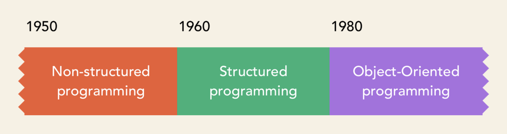
- Unstructured programming
- Structured programming.
- Object Oriented programming.
OOP split apart the program into self-contained objects. Each object represents a part of the system that gets mapped to a distinc entity . Basically, an object functions as a separate program by itself. It operates on its own data and has a specific role.
The objects that form the system interact with each other. Object-orientation aims to bring the world of programming closer to the real world.
10. Objects
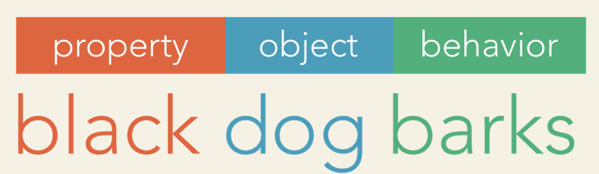
- An Object represent a thing.
- Objects may contain or refer to other objects.
- We can describe objects using their properties.
- All these properties describe an obejct in the real world.
- Objects have their identity, their own state.
- Changing the state of an object does not change of other objects.
- Their state is independent, each has its private identity.
- Besides properties and identity, and object has its own behavior. The behavior of an object is what it can do.
What kinds of things become objects in object-oriented programs? The answer to this is lim- ited only by your imagination, but here are some typical categories to start you thinking:
- Automobiles in a traffic-flow simulation
- Electrical components in a circuit-design program
- Countries in an economics model
- Aircraft in an air traffic control system
- Menus
- Graphics objects (lines, rectangles, circles)
- The mouse, keyboard, disk drives, printer
- Customized arrays
- Stacks
- Linked lists
- Binary trees
- Employees
- Students
- Customers
- Salespeople
- An inventory
- A personnel file
- A dictionary
- A table of the latitudes and longitudes of world cities
- Time
- Angles
- Complex numbers
- Points on the plane
- Cars in an auto race
- Positions in a board game (chess, checkers)
- Animals in an ecological simulation
- Opponents and friends in adventure games
The match between programming objects and real-world objects is the happy result of combin- ing data and functions: The resulting objects offer a revolution in program design. No such close match between programming constructs and the items being modeled exists in a procedural language.
11. The Class
A class is a blueprint of an object.
We created a class by a giving it a name, declaring its properties an actions. We call these actions methods. Methods are blocks of code that can be called to execute certain operations. They may take input parameters and can also return values. Methods are like functions in structured programming languages. The methods are basically functions embedded in a class.


- A class serves as a plan, or blueprint.
12. Abstraction
Abstracion is a way of describing complex problems in simple terms, by ignoring some details.
Focus on essential qualities, discard unimportant ones.
13. Encapsulation
We encapsulate something to protect it and keep its parts together.

In OOP, this translates to packing together our properties and methods in a class. Encapsulation also means hiding the gears and the levers.
We don´t want to expose the inner workings of our class. An object should only reveal the essential features. This concept is called Data Hiding. By hiding its internal details, the object is protected from external interference.
We restrict clients from modifying the object in ways we did not originally plan, whether it is intentional or accidental. Additionally, we prevent other parts of the system from relying on properties or behavior that may change.
If we expose unnecessary details, any changes to those attributes or methods may affect other parts of the system. Whereas if we restricted access to that data or behavior, we don´t have to worry about the ripple effect of our changes.
Small changes can ripple through software to cause major unintended impacts elsewhere.
Data hiding is not about selfishly keeping stuff for ourselfts. It is rather about protecting our classes from unwanted external dependencies.
Expose only as much as your class properties and methods as needed for normal usage.
Data hiding plays an essential role in keeping the dependencies between objects to a minimum.
A tighly couple system, with most of the objects depending on each other, is the obvious sign of a bad design. Updating or maintaining such a system is a pain.
Any tiny modification will cascade down and require you to change other parts of the system, too. It is like a never-ending nightmare.
Encapsulationis usually defined as one of two things,
- A mechanism by which information (code) is hidden.
- A construct for bundling data together.
- The grouping of data and computations on the data into one class is called
encapsulation.

14. Inheritance
- Inheritance means code reuse.
- Object-orientation is about granularity and separation of concerns. Each class should focus on one set of specific functionality and do that well.
- A class can inherit all the attributes and behavior from another class.

15. Polymorphism
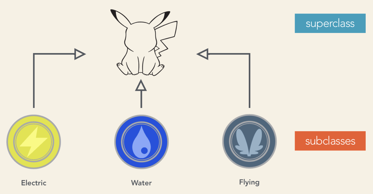
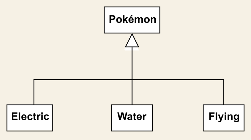
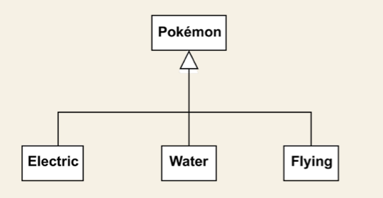
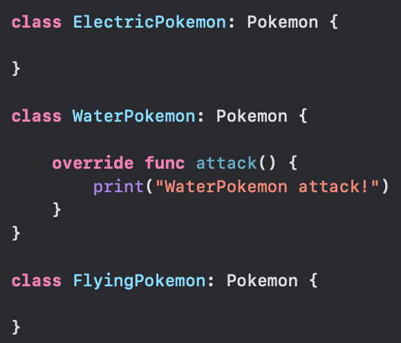
Polymorphism is about working freely with instances of many different classes that share a common superclass.
- The condition of occurring in several different forms.
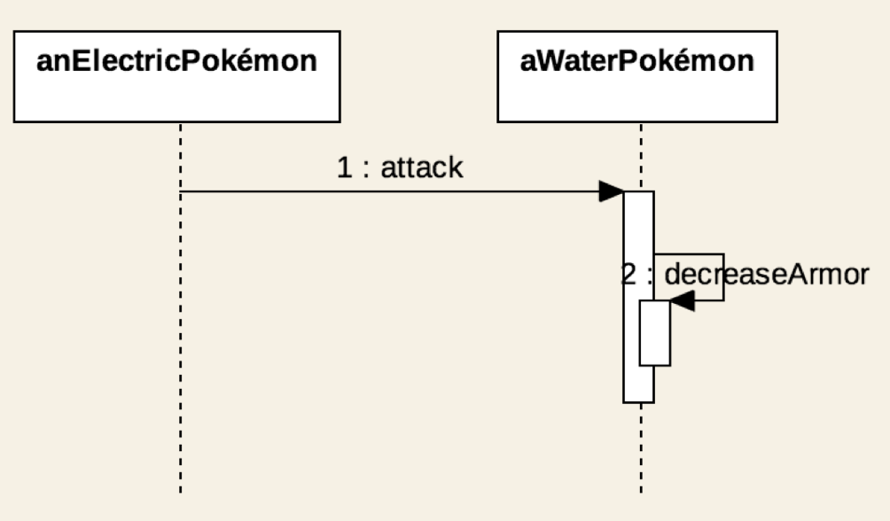
- Polymorphism lets us work with objects created from any of these classes. Using the pokemon example we could create an army of mixed pokemons and tell them to attack at once.
- If we create a list of pokemons, now I can traverse this list and call the
attack()method on the objects in the list. We don´t need to know the class they were instantiated from.
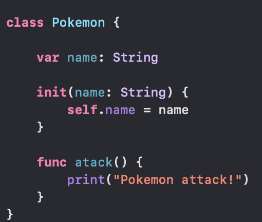
let pokemons = [eevie, pikachu, misty, charizard]

for pokemon in pokemons {
    pokemon.attack()
}
If we run.
Pokemon attack!
Pokemon attack!
WaterPokemon attack!
Pokemon attack!
We see in console that the attack method produced the same output in the console for all the objects but one.
That object was type WaterPokemon, which overrides the attack() method.
- Collect the requirements.
- Describe the software system.
- if Agile
- Accurate description
- Include the creation of visual mockups, wireframes or even prototypes.
- if Agile
- Identify the things that form our system.
- Describe the behavior of our system.
Requirement means "a thing that is needed or wanted". We must clarified what is needed or wanted in our applications.
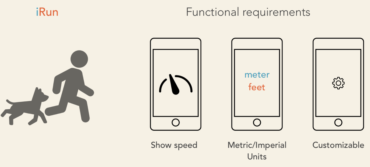
The features of the system are the so-called functional requirements. Functional requirements represent what the app needs to provide feature-wise, how it should react to a particular input, or what is the expected behavior in a specific situation.
Let's say you are about to develop an app for runners. You should answer questions like:
- Should the actual speed always be visible on the main screen?.
- Do we allow imperial and metric units?.
- Should we make this configurable by the user?.
- Or automatically adjust the units based on the phone's settings instead?.
We will usually also have nonfunctional requirements. These are the requirements that are not directly related to a feature or behavior of the software system but are important nevertheless.
Think of performance requirements: you don´t want to ruin the user experience with an unresponsive app.
Also, you may need to address legal requirements. Does the app collect sensitive user data?. Does it allow users to browse the internet?.
Documentation and support are also nonfunctional requirements. Your software may need to adhere to certain standards or regulations.
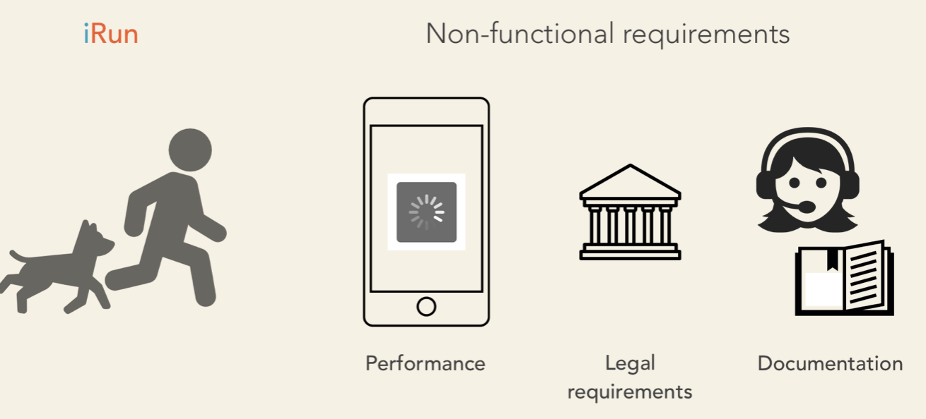
Nonfunctional requirements are equally important. Ignoring them may cause serious legal issues and all sorts of other problems.
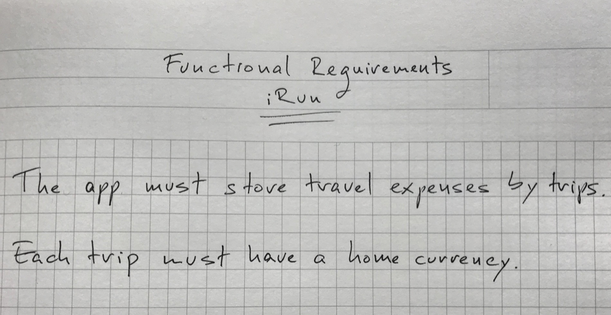
Now, how do you handle this?. There are different ways to gather the requirements. The easiest way is to write them down. Here is an example from a project I have been working on.
- The app must store travel expenses organized by trips.
- Each trip must have a home currency. The default currency is fetched from the phone's settings. User setting must override the default home currency.
- Expenses can be entered in any of the supported currencies. The app must automatically convert the amounts to the home currency.
- The app must run on iOS 9 and newer versions.
- The app must avoid unnecessary network roundtrips to reduce data roaming fees and preserve battery.
- The app must include the support email and the link to the app´s website.
These are short, concise phrases in the form
We don't want to write lenghthy descriptions but you can freely adapt this format to your needs.
You should use some electronic form, but at early stages, pen and paper or a whiteboard are also fine. Just make sure you store them somehow, for example by taking photos.
These are also more formal ways, tools, and systems that support the requirements collection steps. I will not talk about these tools because this book is not about tools, but rather about principles.
To summarize, the requirements collection step boils down to this:
We need to formulate what our software must do and which are the constraints and boundaries we need to consider.
If we are using a waterfall approach, we need to clarify all the requirements in advance. For agile projects, it is perfectly acceptable if we continue without having all teh answers. We may even miss some of the questions. Agile lets us revisit and refine the requirements as we iterate through the software development process.
Once we have gathered the requirements, we can feed them to the next step of the software design process. This is where we provide short, accurate descriptions of our system's functionality from the user's perspective.
One way documenting our system's features is through use-cases.
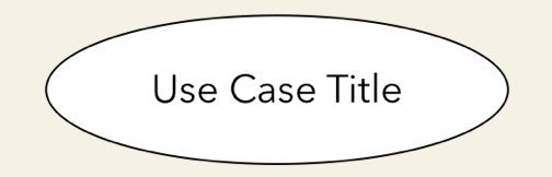
A use-case needs a title. Something like:
- "Create New Trip",
- "Edit expense" or
- "Convert Currencies".
Note that each use case should represent a disctinct functionality.
Next, we define the actor who is using this functionality. We call it a "actor" since it can represent a user who is interacting with tha app, but also a non-human entity, like another system.
Then, we describe the details of this specific use-case. This is called the scenario.
Here we should write one or more sentences that explain what and how the system works in this particular case. Here is an example:
- The user can initiate the creation of a new trip from the main screen.
- The title is mandatory. All the other settings are optional.
- Optionally, the user can write a short description and set a start and end date for the trip.
- The app assigns a default home currency based on the phone's settings. Users can override the default home currency with any of the supported currencies.
- The app allows setting a budget for the trip. This setting is optional.
- Also, the user can assign a custom thumbnail to a trip.
- And the user can save the trip or cancel the trip creation process.
You can write this as a praragraph or as a bulleted list. The format does not really matter. But it is important to avoid technical terms. Again, this description should be understood by all stakeholders, includinh the end users.
The format of the use-case document may vary from company to company. Some may include additional details, but that will not change the essence of it.
The use-case document aims to provide a clear and human-friendly description. What a specific part of the software does and how the actor interacts with it. And this is a textual description. We will talk about the use-case diagrams later.
User stories are another common way of describing certain features or parts of our application. User stories are shorter than use-case descriptions, usually only one-two sentence long. They typically follow this format:
Examples:
- "as a user, I want to add notes to my expenses, so that I can identify them later on".
- "As a power user, I want to retrieve the app´s database file, so that I can inspect it on any computer".
If you can't describe a user story in one or two sentences, you may need to split it into multiple, smaller user stories.
These larger user stories are known as epics. Epics cover a bigger chunk of functionality, like in the following case:
1, "As a traveler, I want to track my expenses while abroad, so that I don´t exceed my budget"
This epic could be split into may user stories including these:
- "As a user, I want to create new trips, so that I can track each of my travels separately"
- As a business traveler, I want to tah my business trips, so that I can separate them from my private travels".
User stories are often written on sticky notes or index cards. You will see them arranged on walls or tables during meetings and discussions.

Unlike use-case descriptions, user stories don´t capture the feature details. They serve as discussion starters instead.
User stories are about communication, and you will usually see them in agile projects. Whereas use-case descriptions are preferably used by Waterfall methodologies.
The first two steps of the object-oriented analysis don´t require any special tool or design language. We only need some text-editing software. Even a piece of paper or a whiteboard would be sufficient to collect the requirements and jot down (anotar) the use-cases or user stories.
The next steps require us to depict the classes that form our system. How they behave and what attributes they need.
 |
 |
 |
|---|
We also need to visualize how the objects interact with each other.
The development community faced this very same problem. The lack of a commonly accepted design language lead to the proliferation of different nonstandard approaches.
We could also try to come up with a way to draw everything from classes to object interactions. Luckily, we don´t have to.
The Unified Modeling Language is a common design language that was released in 1997. UML. UML provides a set of standard diagram types that can be used to describe both the structure and the bahavior of software systems.
We will dig deeper into UML in the upcoming section.
Understanding a software system just by looking at its source code can be very time-consuming, and communicating ideas about software design or business processes is even harder if there is no commonly accepted way to do it.
The Unified Modeling Language - in short UML - was introduced to solve this problem. UML is not a textual programming language, but rather a graphical notation; a set of diagrams that help in designing and communicating software systems.
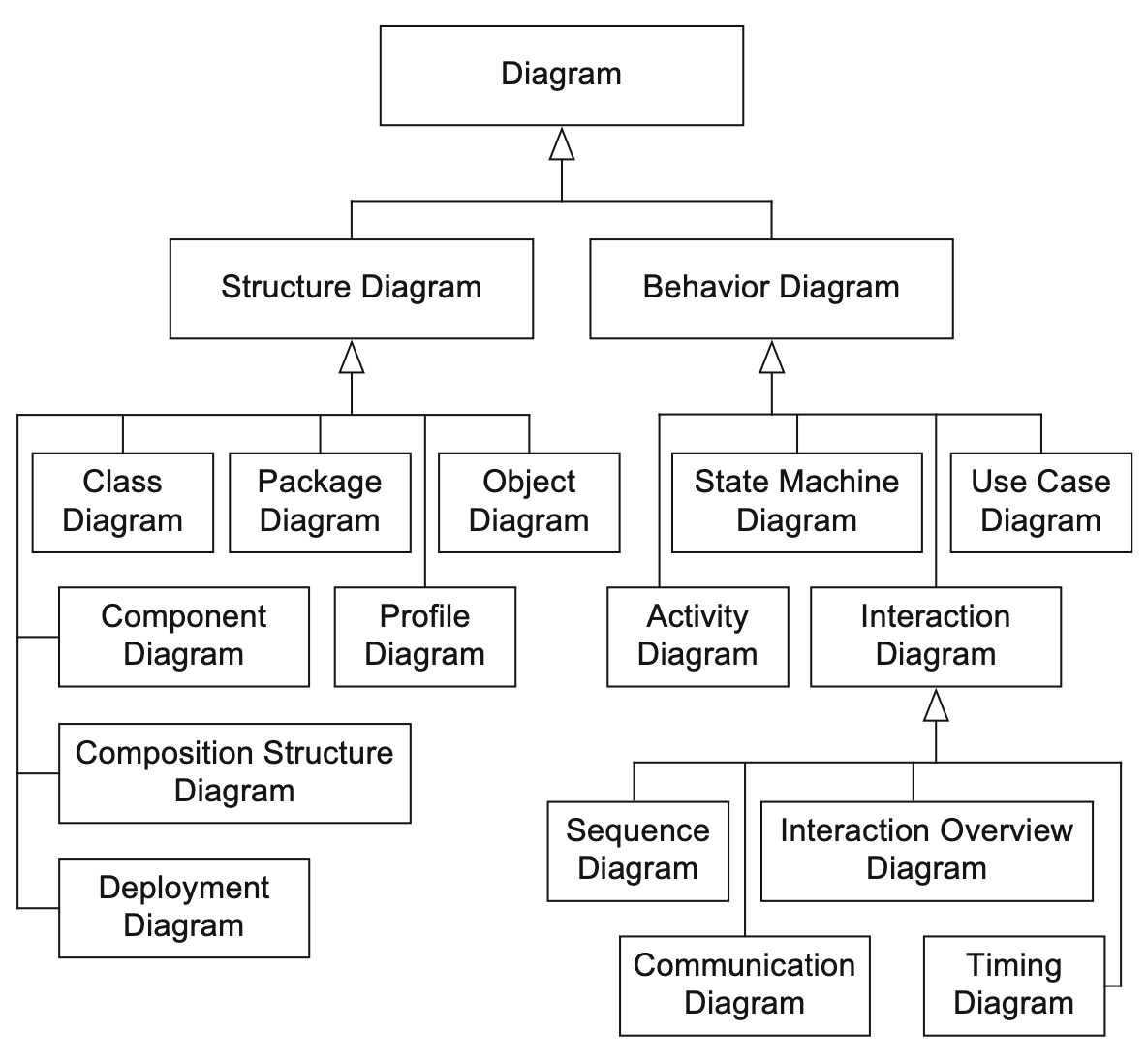
We can use these diagrams to describe the objects that form a system and their interactions. UML has many diagram types. We will be discussing the most common ones.
That is, the functionality of a system from the user's point of view.
To describe the structure of a system. UML provides structural diagrams. We will talk about the class diagram, which can be used to describe the structure of a system in terms of objects, attributes, operations, and relations.
UML lets us model dynamic behavior, too. The behavioral diagrams describe the functionality of the system, focusing on what happens and the interactions between objects.
We will talk about the actual diagrams shortly.
The best part about UML is that it is independent of any particular programming language. We can start coding an object-oriented software based on UML diagrams. If those diagrams are detailed enough, they can be converted to source code.
 |
 |
|---|---|
 |
 |
Now, let's see some ways of using UML in real-life.
We can quickly draw a diagram to sketch a specific part of a software or a new functionality. I did that myself on a numerous occasions. Whenever something was unclear, I started to sketch UML diagrams before writing a single line of code.
The benefit was that I not only understood what I should implement, I also had a design. A documentation that could be used to communicate my ideas with other team members.
Another frequent use of UML is drawing diagrams from existing code. This technique is called reverse engineering, and it helps to understand and document a system.
We can also use UML to create the detailed bluprint of a system. While sketches focus only on the essential aspects of a system, the blueprint is about completeness. Detailed UML blueprints are usually required for software development using a Waterfall-approach and less frequently for Agile projects.
You can use UML diagrams to describe any system that is developed using an object-oriented programming language. UML has become so popular that it is also used for non-object oriented projects.
let´s start with the use-case diagram. It is one of the simplest UML diagrams.
Its purpose is to visualize the functional requirements of the system. Use-case diagrams show groups of related use-cases. Sometimes they may include all the use-cases.
The result is an overview of the system that may include several written use-cases. You will rarely create use-case diagrams for a single use-case description.
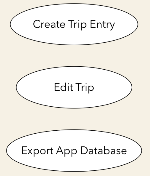
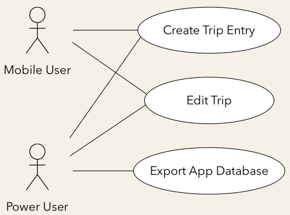
To represent a use-case, we draw an oval in the middle of the screen and put the title of the use case in it.
- "Create a Trip Entry".
- "Edit Trip".
- "Export App Database".
These are examples of use-cases from our Travel Expense app mentioned before.
We use stick figures to represent the actors. As you may recall:
We draw the stick person to the left or the right of the diagram. The actor's name goes below the stick figure.
We usually draw the primary actors on the left side and the secondary ones on the right side of the use-case diagram.
Next, we draw lines to represent the interaction between an actor and a use-case. A mobile user can create or edit a trip entry, but he cannot export the app's database. The power user can perform all these actions.
We need to visualize our system's boundaries if it interacts with other systems. For that, we draw a frame around all use-cases and actors that belong to a given system.
Let's say that we are relying on an external iCloud-based storage. I will represent this external system as a separate actor on the right side. I even changed its visual representation to show that it is not a human actor. Most tools allow you to do that.
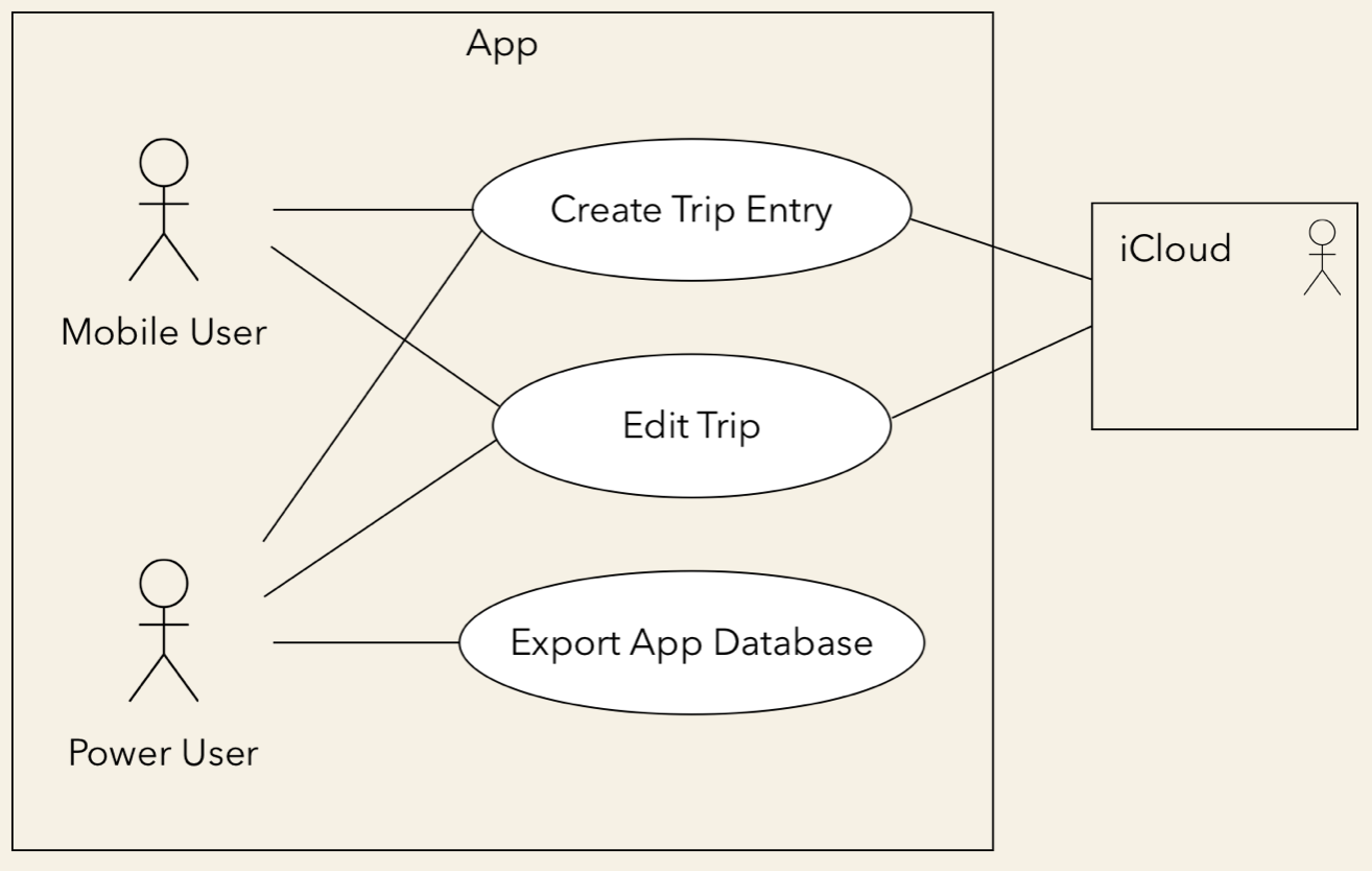
The "Create a Trip Entry" and the "Edit trip" use cases would rely on the cloud to back up their data. So, I connect these use-cases with the external system.
You can quickly tell what our system does just by looking at this use-case diagram.
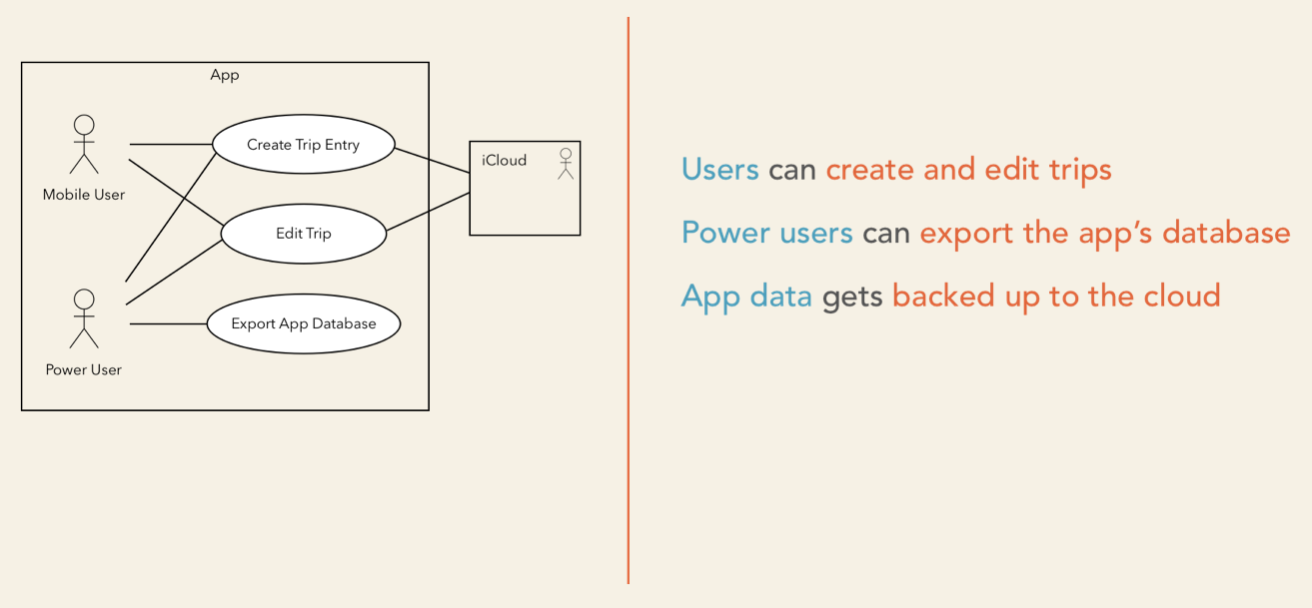
This system lets users create new trips and edit existing ones. Power users can even export the database. The app relies on an external cloud system to store its data.
Such a simple diagram makes it clear what the system does and what it does not do. A customer or a user can easily see if needed features are missing. The absence of use cases shows what the system does not do.
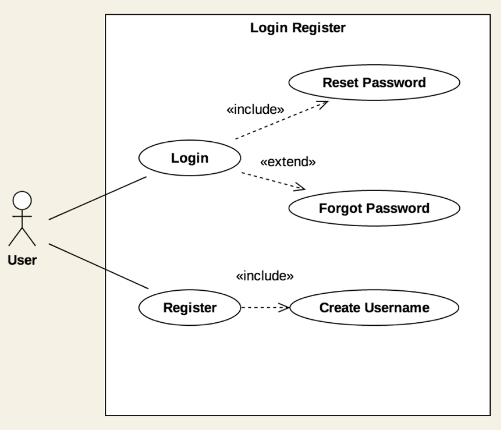
The UML use-case diagram includes other artifacts and relationships between use-cases. We are going to ignore them as they tend to overcomplicate our design and the benefits are questionable.
You can´t go wrong if you focus on the actors, the use-cases, and their interactions. You will be able to easily create your own use-case diagrams and communicate your ideas in a clear and concise way.
They are not a replacement for written use-case descriptions, though. Use-case descriptions include more information to ensure that we don't miss any of the important details or requirements.
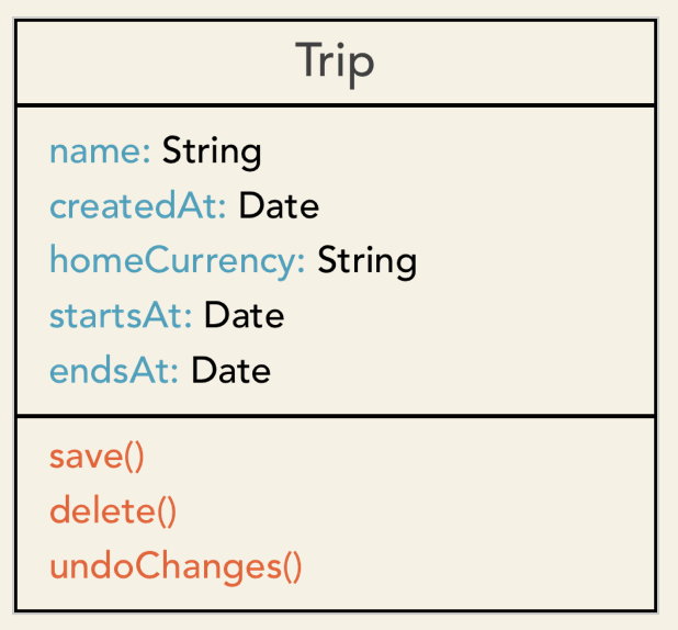
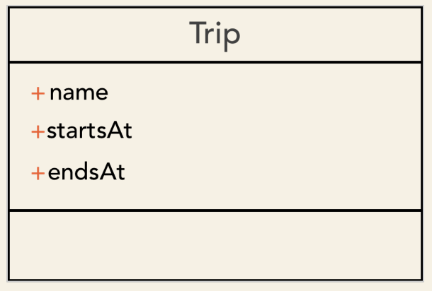
A class is represented on the class diagram as a rectangle with threee compartments. First, we need to list the class's name.
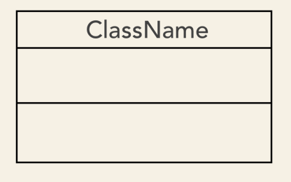
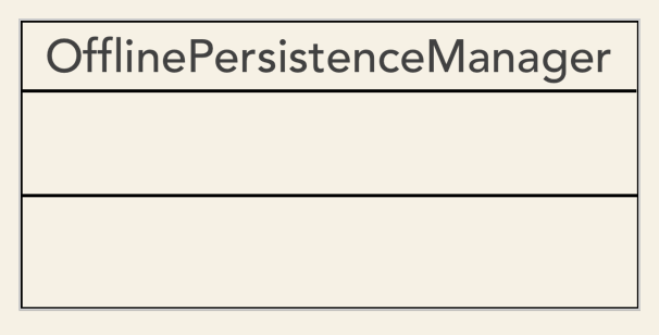
When naming our classes, we must adhere to some rules. These rules are known as naming conventions. A class name should be a noun in the singular, and it needs to start with an uppercase letter.
If the name consists of multiple words, we need to uppercase each world, like in this example:
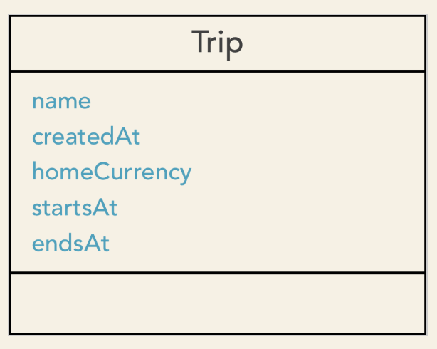
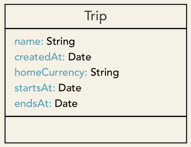
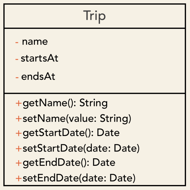
It is useful to specify the type of the attribute. We can do that by writting the data type after the attribute´s name separated by a colon. So, here is our Trip class with the attribute names and types:
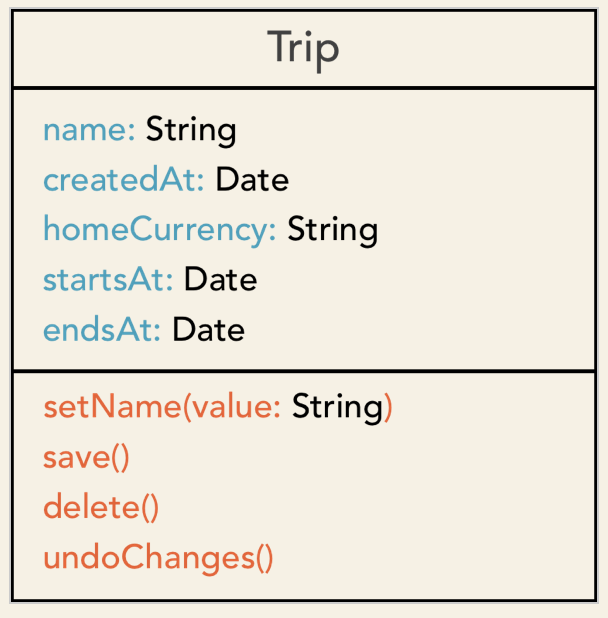
This is where we list the class´s methods. Method names should be verbs in lowerCamelCase.
We can also specify method arguments. The parameters appear within the parenthesis as name-data type pairs, like in setName(value: String)
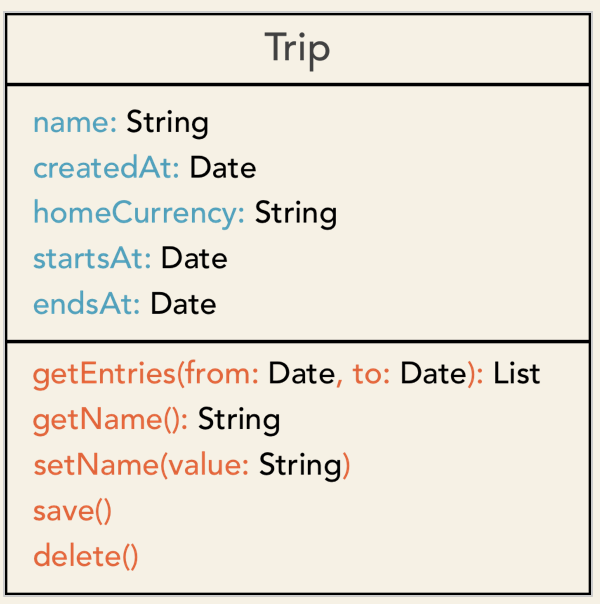
To show a method returns something, we add a colon after the closing parenthesis followed by the return type:
name(): StringAnd we can also have methods that have arguments and a return type.
This is where we list the class´s methods. Method names should be verbs in lowerCamelCase.
We can also specify method arguments. The parameters appear within the parenthesis as name-data type pairs, like in setName(value: String)
To show a method returns something, we add a colon after the closing parenthesis followed by the return type:
name(): StringAnd we can also have methods that have arguments and a return type.
22. Visibility
Now, let´s talk about visibility. UML allows us control who can access the attributes and the methods or our classes.
We have the following visibility levels in UML.
A class method or attribute marked as public can be used by code outside of the project.
Private attributes and methods can only be used within the class that defines them. Elements marked as private can't be accessed directly from other classes.
Protected visibility means that only child classes (and the defining class) will be able to access that attribute or method.
Which makes sense in some programming languages that let us group our code into logical units and provide a namespace for this group. Using package visibility, we make our elements available within its enclosing package.
UML provides these visibility tags, but its up to us to adapt it to the language we are using. There is one rule that is commonly applicable to all object-oriented languages: You should only expose as much as needed and hide everything else.
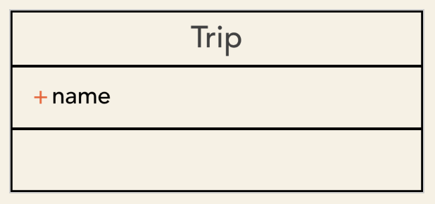
Class attributes will usually have private or protected access. We should provide public setters and getters instead of allowing everybody to access our class´s data. This lets us control what the callers do with our class´s attributes.
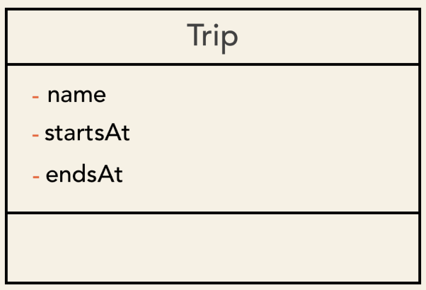
In our Trip class, we could make the name attribute public. Callers could set and retrieve it, which seems to work as expected.
But, what if we need to make sure that a Trip´s name is never shorter that say three characters?.
name.length >= 3There is no way to enforce this requirement.
Another example. The trip´s start date needs to be earlier that its end date. Yet, callers can freely set any start or end date.
name.length >= 3
endsAt >= startsAt
I´m going to change the visibility of all these attributes to private. Now, we can access them exclusively from within the class`s own methods. After this change, other objects can´t set or retrieve these attributes. They are, well, private to the Trip class.
Awesome! But then, ho do we set, retrieve or modify them?.
Here is the solution: I provide public getters and setters for each of these attributes:
I will change getName name method to name, as objective-c convention.
Now we can check whether the name is at least three characters long by validating the name parameter in the setName() method. If it is shorter, we just print a warning message and return.
[insert code, check Visibility.playground]
Also, we validate the start and the end date in the corresponding setters.
[insert code, check Visibility.playground]
We are now in full control of our class´s internal data. Setters let us check the input argument, and getters allow us to modify the value before returning it.
For example, we could return a date in the user´s timezome.
So far, we have seen how to represent a single class. Class diagrams let us also show the relationships between the classes in our system. We will talk about relationships next.
23. Associations
The next logical step after identifiying the key classes in our system is figuring out the relationships between them. Use-cases or user stories will help us during this process.
Here is one of the functional requirements of the TravelExpense app.
"As a traveler, I want to track my expenses while abroad, so that I don´t exceed my budget"
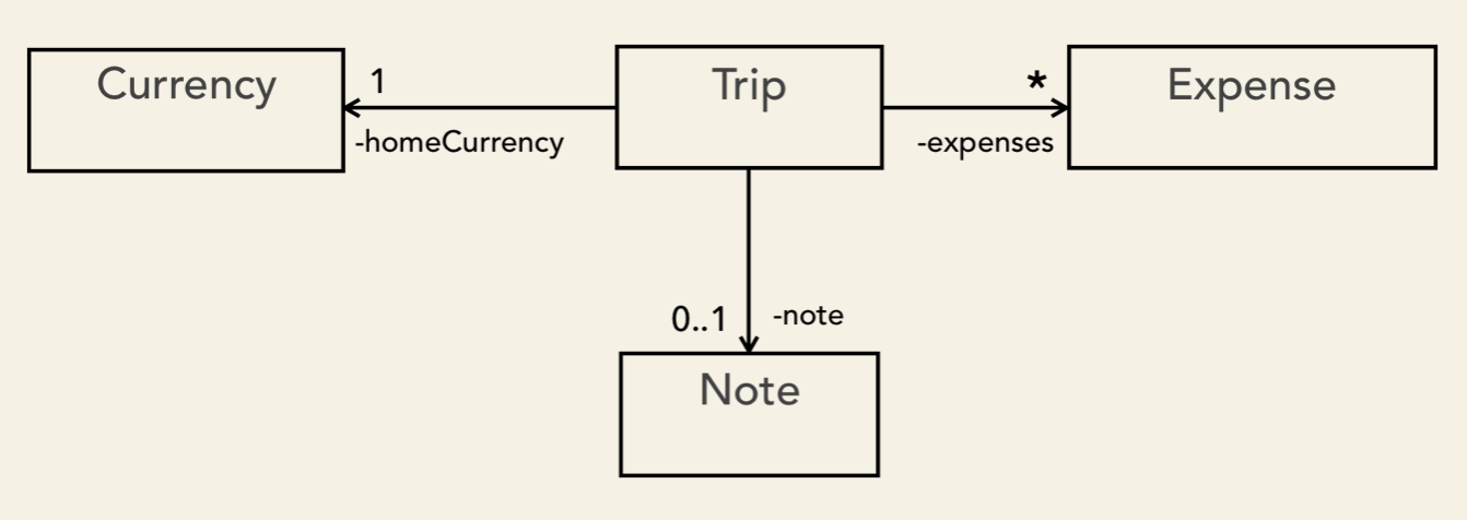
We have a Trip and an Expense class. Each trip will include it´s travel expenses. So, there needs to be some relationship between the Trip and the Expense class.
To express this relationship, we draw a solid line between these classes.
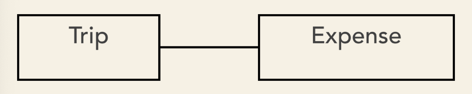
This line represents an association. The association tells us that the classes refer to each other.
We can be more specific here. The Trip class needs to know about its expenses.
We have already talked about the drawbacks of tightly coupled systems. Tight coupling is something that you should definitely try to avoid. Let me ilustrate the issue it causes.
Coupling. As opposed to cohesion, the coupling of a module in a system is related to the amount of connection between the elements of a module and the elements of the rest of the system. The interconnections may be direct or transitive. So, adding a relationship, whether internal to the module or belonging to its set of outer relationships, can never decrease coupling.
The Trip refers to the Expense class. That is fine, since a trip can have expenses associated with it. What happens if also the Expense refers to the Trip class?.
Cohesion. Cohesion is related to the degree and not the extent with which the elements of a module are tied to each other. Thus, cohesion measures are normalized.
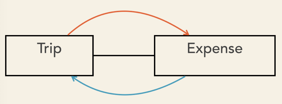
Because of this reference, if we tried to use the Expense class in other parts of the system, we would need to also bring the Trip class with it.
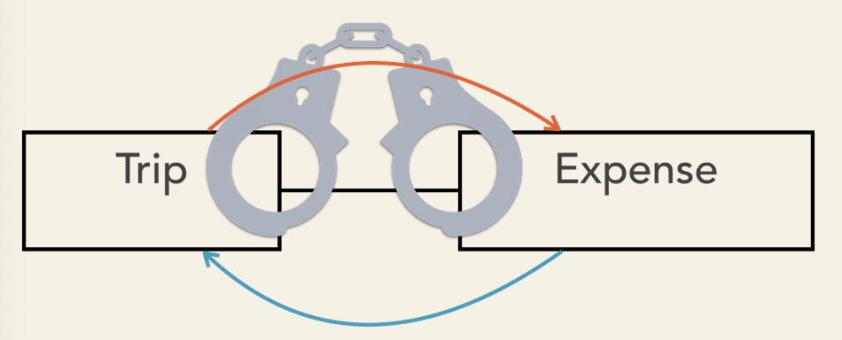
This does not make sense, as we should be able to use an Expense without a Trip.
UML let us express direct associations. By drawing a solid line that ends with an open arrohead, we show that only one of the classes refers to the other one. The arrow points to the class that is referred to by the other class.
Let's change it to a directed association.
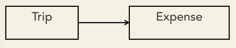
Now it shows that the Expanse is associated with the Trip, but the Expense class does not know anything about the Trip class.
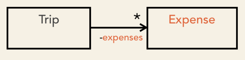
A Trip will usually have multiple expenses. We can represent the multiplicity of associated objects as follows:
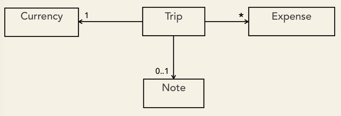
Associations can show multiplicities at both ends of the line.
If there is no multiplicity shown, you can safely assume it is one. We can also display the name of the class property for the given application.
The association is not the only kind of relationship we can have between classes. Next, we are going to talk about generalization.
24. Generalization
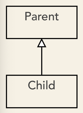
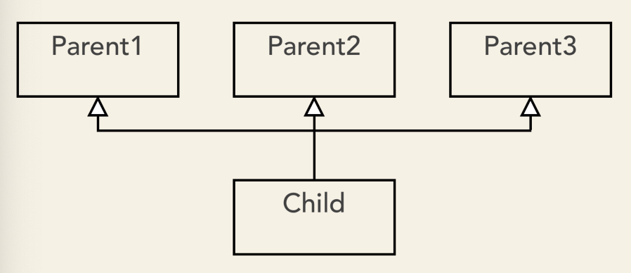
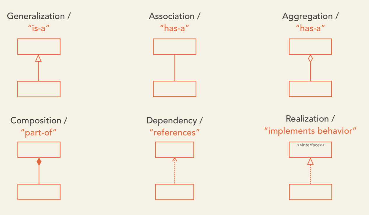
In UML, we use generalization to express that one model element is based on another model element. Generalization is represented as a solid line with a hollow arrowhead that points to the parent.
Let's say that we need a special Trip class for our business trips. BussinessTrip would inherit from the Trip class and this is how we represent in UML:
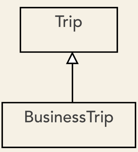
Because BussinessTrip inherits everything from its parent, we must only specify the attributes and operations that are specific to the child.
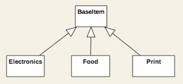
A parent can have multiple children.
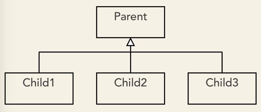
And we can also have child classes that inherit from different parents.
Some programming languages support multiple inheritance; C++, Perl, Python - just to name a few.
Many modern programming languages only allow single inheritance, that is, inheriting from one parent class. Single inheritance reduces complexity and avoids the ambiguity that comes with multiple inheritance.
Some argue that multiple inheritance has more benefits than drawbacks. However, it is certainly easier to make mistakes when using multiple inheritance.
UML does not restrict generalization to classes. It can also be used in use-case or components diagrams. This let us indicate that a child element receives it's paren's attributes, operations and relationships.
We talk about a dependency relationship if changes in one of the classes may cause changes to the other.
In UML, dependency is represented as a dashed line that ends with an open arrowhead. The arrow points to the dependency.
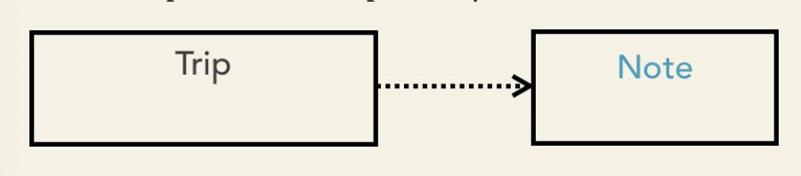
A dependency is a directed relationship.
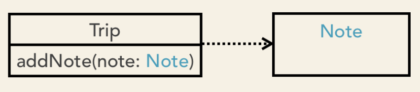
Dependency is often confused with Association, but there is a big difference. Association indicates that a class has an attribute of the other class's type.
Whereas dependency is usually created when a class receives a reference to the other class (for instance, through a member function parameter).
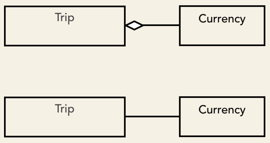
Aggregation represents a part-whole relationship and is drawn as a solid line with a hollow diamond at the owner's end.
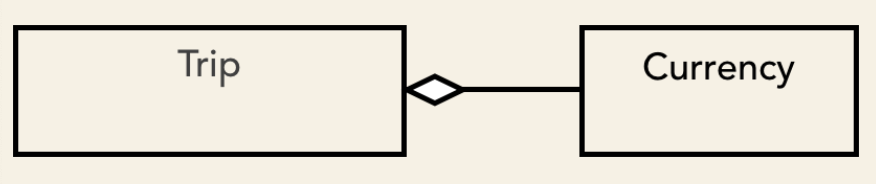
This relationship is considered redundant because it expresses the same thing as the association. So, these two diagrams are equivalent:
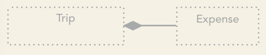
Composition is a stronger form of association. It shows that the parts live and die with the whole. In other words, composition implies ownership: when the owning object is destroyed, the contained objects will be destroyed, too.
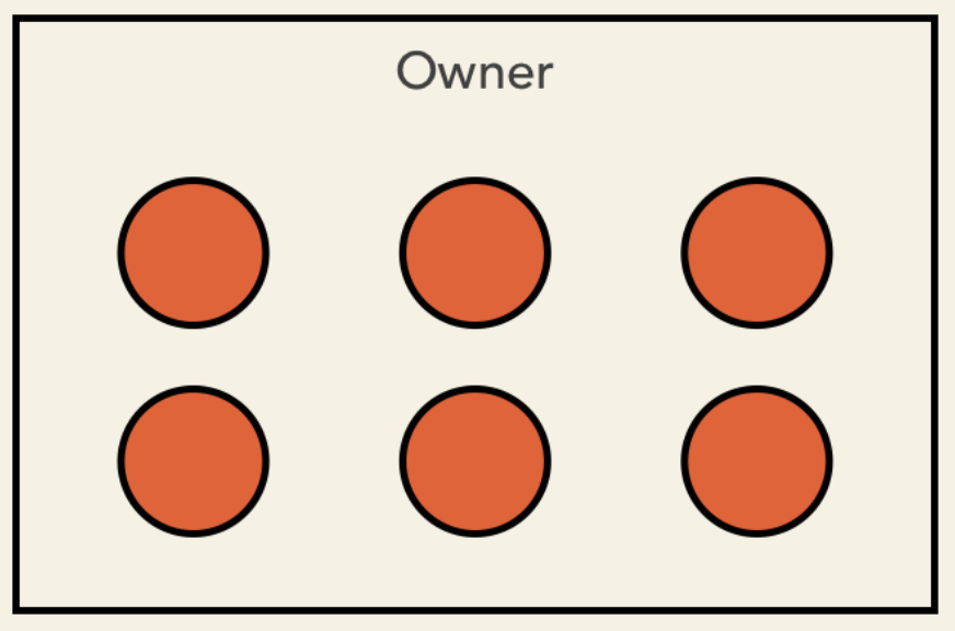
The composition is represented as a filled diamond on the owner's end connected with a solid line with the contained class.
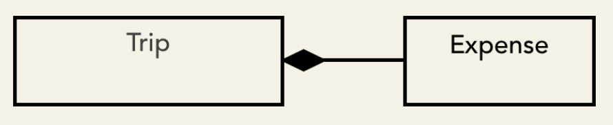
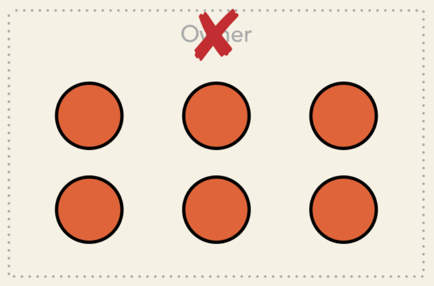
The Expenses of a trip can't exist without the Trip. If we delete the Trip instance,
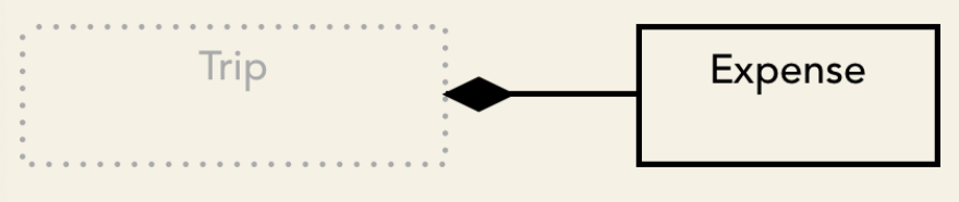
its expenses are going to be removed, too:
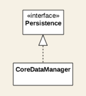
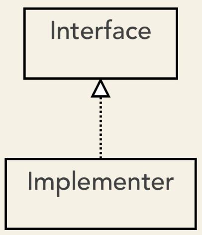
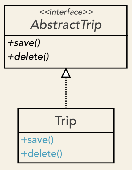
Realization indicates that a class implements that behavior specified by another model element.
It is represented as a hollow triangle on the interface end connected with dashed lines with the implementer classes.
We could specify an interface to ensure that all current and upcoming trip classes provide a common set of methods. This is a useful feature that allows polymorphic behavior.
Here is a quick summary of the relationships and their graphical representation:
Use case and class diagrams are static diagrams. They are great at representing the structure of our system.
What if we need to show how the objects interact with each other?. When are objects created and for how long are they around?. Static diagrams can´t answer these questions.
UML provides dynamic diagrams to represent how objects communicate with each other. The most common dynamic diagram is the sequence diagrams.
We use the sequence diagram to describe the flow of logic in one particular scenario.
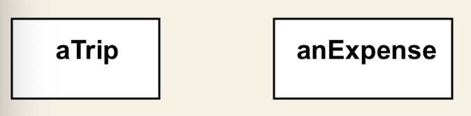
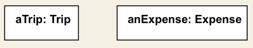
A sequence diagram starts by drawing boxes at the top of the page. Each box represents an object. Since these are objects, we name them differently. "aTrip" instead of "Trip" and "anExpense" rather than "Expense".
We can also display the type after the instance´s name separared by a colon. This may be helpful in some cases:
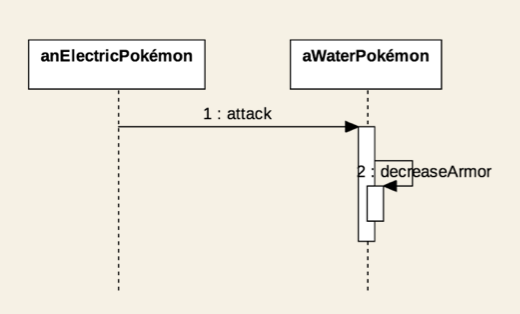
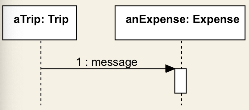
The lifeline of an object is represented by the dotted lines beneath each box. This line shows the time the instance exists during the scenario. The sequence diagram also lets us show the message sent from one object to the other. A message is basically a method call.
Now, let me illustrate the various messages in a practica example.
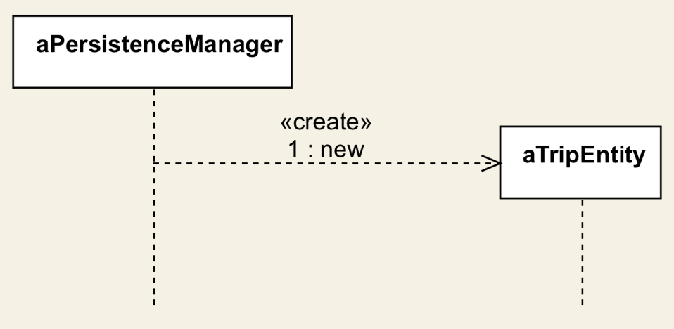
I will be using StartUML, a UML diagramming software. Let's assume that we have a persistenceManager object. This objetc is responsible for storing and retrieving entities in the app´s local database.
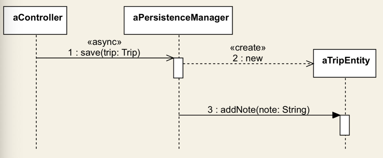
The persistenceManagerneeds to create and store a TripEntity instance. First, I add the TripEntity object. The persistanceManager instance sends a create message to initiate a tripEntity object. The create message is represented as a dashed line with a stick arrow head.
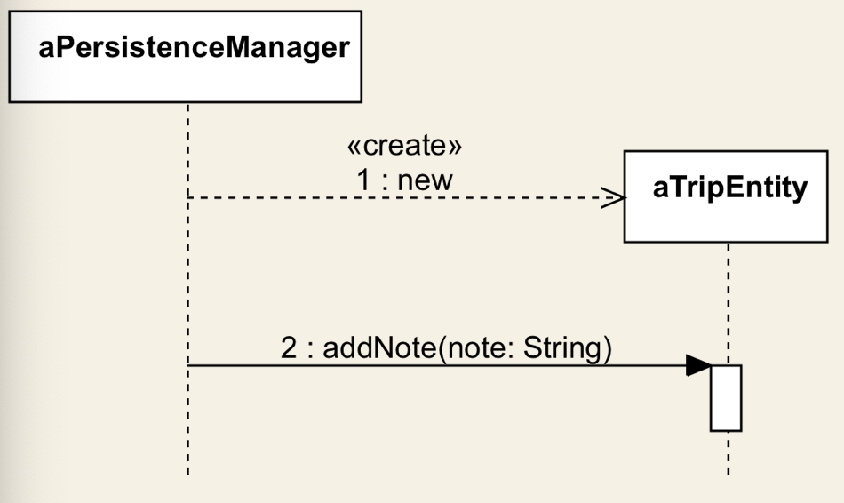
Next, the persistence manager sends a regular message to the already created trip entity. This message corresponds to calling the addNote(nod: String method on the TripEntity instance. A regular message is shown as a solid line with a filled arrowhead. We can add parameters to our message if we wish:
Although we could display the return message, only do it if it is important. Return messages are implicit for synchronous messages, so we don´t have to display them.
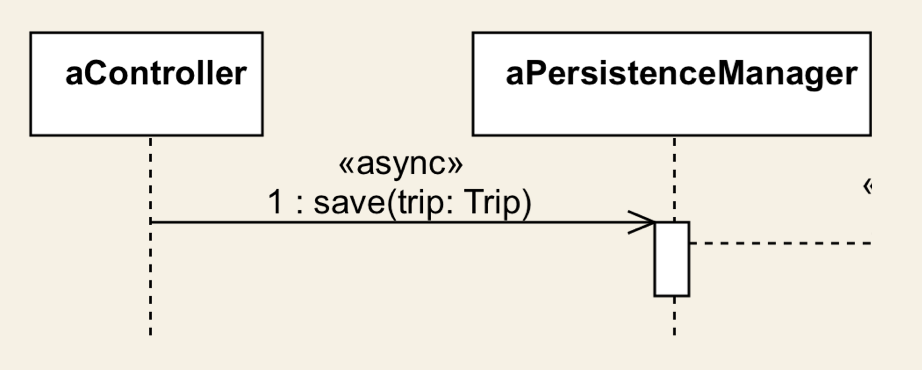
Asynchronous messages are drawn as solid lines with a stick arrowhead. The controller object sends an async save(trip: Trip) message to the persistanceManager. Disk operations are slow, so inserting a new record into the database is a perfect candidate for an async call.
When an object sends any async message, it does not need to wait for a response. The asynchronous call gets executed in the background, and it returns once it completes. Unlike asynchronous calls, it does not block the caller.
Asynchronous behavior stands at the core of modern software system. They improve responsiveness on multicore processors and provide better user experience because lengthy operations won´t block the user interface.
So you will problably draw async messages a lot. The issue is that the difference between regular and async messages is very subtle: stick arrowhead instead of a filled arrowhead. To aovid misunderstanding, you can add an extra note to make it visible it is an async message.
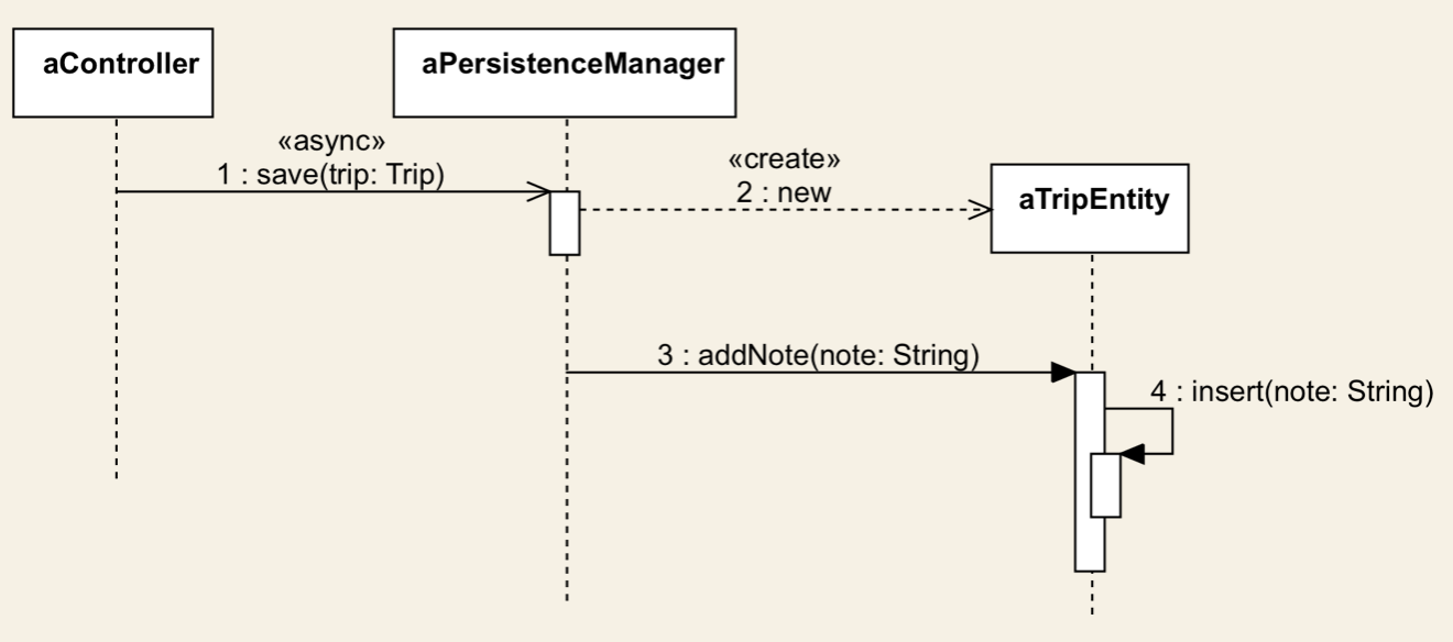
We also have self messages. These represent a method calling another method of the same object.
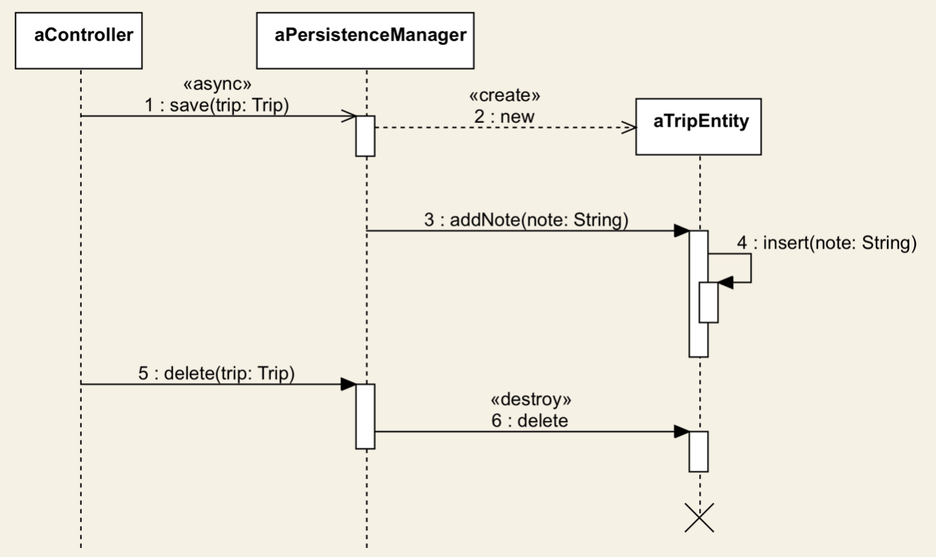
An object can also send a delete message to another object. The persistenceManager sends a delete message to the tripEntity gets destroyed, and its lifeline gets terminated by a cross symbol.
Sequence diagramas should provide an overview of what is going on in a given scenario. We don´t try to represent all the method calls precisely. Insted, we focus on the most relevant parts.
Sequence diagrams help us in clarifying the interactions between objects in a specific scenario. By getting more profound insights into the inner workings of our objects, we may need to refine their behavior. Or even add new classes or establish new relationships betweem our classes.
And that is perfectly fine. The process of designing a software system is all about finding out what is missing, what needs to be enhanced or changed.
Activity diagrams can be used to describe workflows. The actions are represented by nodes. We start an activity diagram with an initial node drawn as a small, filled circle. We can then transition to the next node. The transition is called flow, and it is shown as a line that ends with an open arrowhead. The arrow points the direction of the logic flow from one action to the other.

Activity diagrams can also express conditional logic. We model a decision node as a diamond. It has a single incoming flow and two or more outbounds flows.

Each outbound flow has a guard, which is a Boolean condition placed inside square brackets. The guards need to be mutually exclusive. Whenever we reach a decision, we can choose only one of the outbound flows.
After a decision, the flows can be merged using a merge activity. A merge has multiple input flows and a single ouput flow.

Activity diagrams support parallel behavior. To express current flows, we use a fork drawn as a thick horizontal line. A fork has one incoming flow and several outgoing concurrent flows.

We need to synchronize the tasks that execute concurrently. For example, we can not display the image while it is being read from the local persistence or downloaded from the server. A join represents a syncronization point.
The final node represents the end of the workflow.

The following activity diagram describes a simplified version of the trip creation process.

We begin with the initial node. The user decides to create a new trip.

Next, he is asked to type the trip´s name. Now, the app needs to check whether a trip with the same name already exists.

If it does, we prompt the user to enter a new name or cancel the trip creation process. If he decides to cancel the flow, we end the activity. Otherwise, we validate the name again.
If the trip name is not taken, we let the user fill the remaining trip data. Finally, the user hits the save button. We may want to let him cancel the process here.
Now, I will use a fork to show that we perform some actions in parallel. Storing the new trip into the local persistence and uploading it to the cloud server happen concurrently.

If both actions suceed, we inform the user about the successful trip creation, and we are done.
We can add more details and further actions to our activity diagram if that is useful. The activity diagram is a useful technique to represent behavioral logic. I would not recommend it when working with nontechnical peope, though.
The StateChart or State Machine diagram models how an object transitions from one state to another over its lifetime.
It describes the state changes of an object in response to certain events.
A state is a condition in which an object exists. Think of objects states like New, Pending Changes, or Completed.
These states can change when some event gets triggered. The Pending Changes state transitions to Saved after a successful saved event.
And the Saved state will change to the final Terminated state if the object is deleted.
The state machine diagram starts with an initial state. This is not a real state, but rather the entry point. States are drawn as a rectangles with rounded corners with the state´s name. The transitions from one state to another are shown as lines that end in an open arrow.

Each transition can be labeled with an event name and a guard.

The guard appears between angle brackets; it is a Boolean condition that needs to be true for the state change to ocurr.
Let´s assume that pending changes can only be saved if the device is connected to the internet. We can represent conditional logic in statechart diagrams as follows:

The final state shows the state machine is completed an it also implies the deletion of the object.
Use statechart diagrams to describe the object states of a system while identifying the events responsible for the state changes.
In this chapter, I walk you through the process of designing a note-taking application.
We will start by collecting the requirements and writing user stories. We are going to analyze the system from various angles.
By the end of this chapter, we will have created several UML diagrams that describe the structure and the behavior of our software.
This is going to be an interesting exercise as we put into practice what we learned so far.
In this lecture, I am going to ilustrate the requirements collection phase through a real example.
Let's start by thinking about the features of a note-taking application.
First, we are going to be creating and editing text-base notes. But we don't want to create the next boring note-taking app.
So, let's get creative and add some interesting features.
- How about adding to our notes? and capturing hand-drawn sketches would be a cool addition too.
- Privacy has become increasingle important. We should allow the storing of sensitive notes.
- Automatica syncing to Dropbox, iCloud or Google Drive? sure, many users will find that a useful feature.
Now that we have some ideas floating around, we can come up with a first draft of our destilled requirements.
- We need to build a note-taking app. Users can create an edit text-based notes. A note may also include images or hand-drawn sketches.
- Sensitive notes can be protected from prying eyes using a password.
- The app automatically uploads changes to pre-configured servers. We should suppor all major platforms: Dropbox, iCloud and Google Drive.
Next, let's talk about the nonfunctional requirements.
- Let's release our app for iOS first. We will support iOS 10 and newer versions. The app needs to run on the iPhone and the iPad as well.
- We will create a dedicated support website and include the link in the app's description and its "About" page.
Now that we have collected the requirements, we can proceed to the next step. We are going to map these requirements to technical descriptions.
Now that we have gathered the requirements, we will be writing user stories. So, let's get started.
These are the functional requirements:
- We need to build a note-taking app. Users can create an edit text-based notes. A note may also include images or hand-drawn sketches.
- Sensitive notes can be protected from prying eyes using a password.
- The app automatically uploads changes to pre-configured servers. We should suppor all major platforms: Dropbox, iCloud and Google Drive.
Considering these requirements, we identify three major topics:
- Note creating and editing
- Privacy - protecting user data
- Syncing to cloud servers
These are all big chunks of functionality that can't be described through single user stories. Thus, I'm going to create an epic for each. As you may recall, an epic consist of multiple user stories that describe common functionality.
- As a user, I want to create and edit notes so that I can quickly jot down my thoughts.
- As a user, I want to attach photos to a note so that I can keep my memories in one place.
- As a user, I want to add handwritten sketches so that I can insert funny tooms into my notes.
- As a user, I want to create private notes so that only I can access them.
- As a user, I want to protect my sensitive notes with a password.
- As a user, I want to sync my notes across my iOS devices so that my data is up-to-date on all of them.
- As a user, I want my notes automatically uploaded to cloud servers (Dropbox, Google Drive or iCloud) so that I have a backup of all my data.
These user stories are technical descriptions that serve as a starting point of our use-case diagrams.
Up next, I'm going to show how we might go ahead and map these user stories to actual use-case diagrams.
In this lecture, we are going to represent our user stories as use-case diagrams. Let´s start with the first epic:
- As a user, I want to create and edit notes so that I can quicly jot down my thoughts.
- As a user, I want to attach photos to a note so that I can keep my memories in one place.
- As a user, I want to add handwritten sketches so that I can insert funny things into my notes.
Let´s map these user stories to a use-case diagram.
The actor is the user of this app. Next, I add the use-cases: "Create Note" and "Edit Note".

We also need an "Attach Photo" and "Add Handwritten Sketch" use cases. Now, these are not standalone use-cases. We can´t attach a photo or add a handwritten sketch without creating or editing a note. Thus, I represent them as included in the "Create Note" and "Edit Note" use-cases.

Let´s continue with the second epic.
- As a user, I want to create private notes so that only I can access them.
- As a user, I want to protect my sensitive notes with a password.
Again, we need an actor; It is the user as usual.
The creation of private notes is a special case of note creation. We can represent the "Create Private Note" as an extension of the regular "Create Note" use-case.

Wee need to protect sensitive notes with a password, so I created a "Protect with Password" use case for it. This use-case should be included in the Create Private Note use-case, so I draw it using and include relationship.

Here is the third epic:
- As a user, I want to sync my notes across my iOS devices so that my data is up-to-date on all of them.
- As a user, I want my notes automatically uploaded to cloud servers (Dropbox, Google Drive or iCloud) so that I have a backup of all my data.
This epic is about synchronizing data with a server. This server is another actor, a non-human one. I will represent it on the right side of the diagram using this special format.

Let´s determine the use-cases.
So, whenever we create or modify a note, it needs to be sync´ed with the server.

That is an over simplification, but it illustrates what needs to happen in this scenario. As you may recall, use-case diagrams are a means to share our ideas with nontechnical people, so try to keep it simple.
Next, we get into more technical details, as we will start to identify our test cases.
Let´s create the static structure of our system. We will identify the main classes and the relationships between them.
Our app is about taking notes. So, we will need a class that represents a Note.

A Note has a text. So, I add a private attribute called "text" of type String. As you may recall, we should not expose class properties. Hence "text" is private.

What else do we know?. Let´s take a look at the use-case diagrams we have put together.

We also need an "Attach Photo" and "Add Hanwritten Sketch" use case. A Note needs to have an attribute for the photos and one for the handwritten sketches.
I am using the plural form: photos and sketches. That is, A Note may have many photos and hand-drawn sketches attached to it, I will make these attributes of List type.

The photos attibute is a List of Image type. I introduce an Image class, which can later be changed to an existing type. In iOS, that would be UIImage, but that is not important. The point to identify the potential classes that play a role in our system.

Simililarly, we need a list of sketches. The Sketch class represents our hand-drawn sketches.

The Note class needs some methods:
setText(text: String)to set the Note´s text andgetText(): Stringto retrieve the text.addImage(image: Image)to attach a new image andgetImages(): List<Image>to retrieve all images of a Note.addSketch(sketch: Sketch)andgetSketches(): Listto get the hand-drawn sketches of a Note.

We don´t know anything yet about the underlying format for the Image and the Sketch class.
And that is fine. We need to abstract things first and iteratively refine it. At the end, we may store our hand-drawn sketches either as a JPEG image. But requirements may change and we will need a vector format, so we will use PDF.
Again, we should not go into such details at this stage or we may easily get stuck. This phenomenon is well-know and it even has a name: analysis-paralysis.
Start with a few broad strokes instead of overthinking and spending too much time on figuring out the details right away. Then try to get more specific as you understand more.
Now,
- let´s think about the relationships between these classes?.
- Is there an association between the Note and the Image class?.
- or rather a dependency?.
The Note class has an attribute that refers to the Image and the Sketch class. It did not receive instances of these classes as parameters to a method, so it is not a dependency relationship.
So, is it an association?. Yes, it is. But let´s dig a but deeper.
What happens when we delete a Note object with its images and sketches?. They will be destroyed, too. It does not make sense to keep them if the user decides to remove the Note.
That means that the images and the sketches live and die with the Note object. As you may recall, this is the "part-of" relationship called composition.

Now, an Image does not need to know about the Note. Nor does the sketch. So, these are directed relationships.

Based on the second epic, we need a specialized Note that holds sensitive data.
- As a user, I want to create private notes so that only I can access them.
- As a user, I want to protect my sensitive notes with a password.
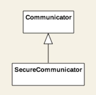
This note shares most of the attributes an behavior associated with the Note class. This looks like a perfect candidate for inheritance.

SecureNote inherits from the Note class. In addition to the inherited attributes, it has property called passwordHash.

Storing the password in insecure. Instead, we store the password´s hash value. The hash is generated using a one-way hashing algorithm from the password. The password can´t be reconstructed from its hash value.
For the hashing algorithm, I am going to define a Crypto class. It provides the public hash method that takes a String as input and returns its hash value. The SecureNote is going to relay on the Crypto utility class to create the password hash. I indicate this as a dependency between the SecureNote and the Crypto class.

Next, we need a class that is responsible for storing the notes and their associated data in the local persistence. We don´t want to be too specific at this point as we have not defined yet what local persistence means. It could be the filesystem or an SQLite database. We could also choose CoreData
That is not important at this point, so we will use abstraction. Instead of specifying a concrete file or database manager, I am going to create an interface that defines a couple of methods.
Let´s call it LocalPersistence. It is an interface: It declares the method signatures that need to be implemented, but it provides no functionality. The implementation classes will be responsible for implementing these methods. The LocalPersistence declares the following interface:
getNotes(): List<Node>- retrieves all notes from the local persistence.save(note: Note)- stores a note locallyupdate(note: Note)- updates a note that has been persisted.delete(note: Note)- removes a note from the local persistence.
All these methods have parameters or return values of type Note. Thus, we can draw a dependency relationship between the LocalPersistence interface and the Note class.

Let´s say that we decide to store our notes in the file system. The FileManager implements the methods declared in LocalPersistence. I use the realization relationship to show that.

Similarly, I will create an interface for the cloud syncing feature. The NetworkController interface declares the methods that take care of the networking related operations*:
fetchNotes(): List<Node>- fetches all notes from the server.upload(note: Note)- uploads a new note to the server.refresh(note: Note)- updates the note tha has been uploaded.remove(note: Note)- deletes a note from the server.
Networking is slow, so these should be implemented as asynchronous operations.
(*) Network controllers are more complex but let´s keep it simple for this example.

By now, you have probably got an idea of how class diagrams are created. Now that we mapped the static structure of our system, we can start analysing its behavioir.
I´m going to walk you through the creation of the sequence diagram for one specific scenario: adding a new note.
We will be focusing on the flow of note creation. We try to answer the following question:
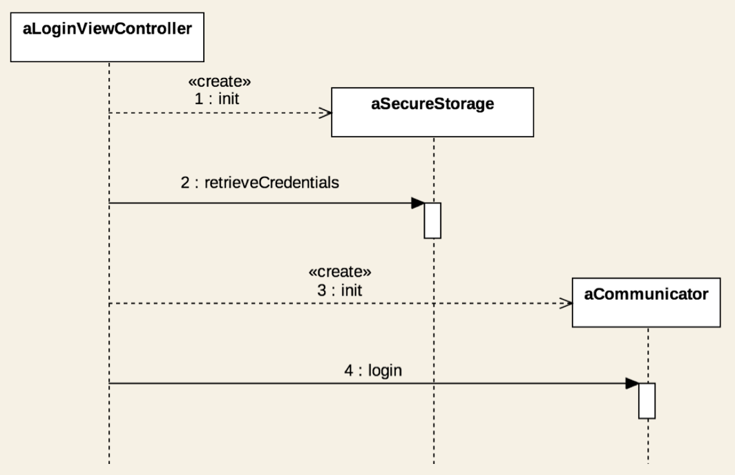
The user can initiate the note creation by pressing a button on the application´s UI. So, we need a view instance first that represents the button. The button receives the user input and triggers and event that is intercepted by a controller object.

Having separate view and controller objects stands at the core of a well-known architectural desing pattern called Model-View-Controller. The view displays data and receives user input. The controller triggers actions based on events received from its view and processes the data to be displayed.
In our scenario. the Controller triggers the creation of a new Note instance. We will use a create message rather tha a regular one. A note object gets created.

Next, the user fills the Note´s details and presses the save button. This will trigger two actions: saving to the local persistence and uploading the new note to the cloud.
Local persistence is managed by the FileManager object. I invoke the save(note: Note) method. File operations are slow, thus I call the save method asynchronously. To avoid misunderstanding I mark the message explicitly as async.

For the upload part, we need an OnlineManager instance. The upload(note: Note) method gets executed in the background, too.

The saving to local persistence and uploading the new Note to the cloud are asynchronous, so they return instantly , without blocking the caller. Eventually, they return to signal either success or failure.


This sequence diagram tells us a lot about the objects and how they interact in the note creation scenario.
We can provide more details by adding further objects and messages as needed.
Let´s take a closer look at the possible states of a note object. A note object is created, saved and that´s it, right? Well, not quite. Let´s start analyzing the possible states and what could go wrong. We will soon realize that we need to represent more states than we originally assumed.
The Note object´s statechart diagram starts with an initial state. When we create a note, it is in the New state. This condition is triggered by the creation event.

After a new note is created, the user needs to fill in some details. At the end of this process, the note will have unsaved changes. We need a state to express this condition.

Now, the user can save the Note. He may also decide to cancel the process, which means that our state machine reached its final state.

Saving a note implies storing it in the local persistence and uploading it to the cloud. These are two actions that could potentially fail.
If both fail, the state of our Note object turns back to Unsaved Changes. Otherwise, we switch to the Persisted & Uploaded state.

Storing a new note in the filesystem will usually complete without issues. However, uploading data to a server could fail for various reasons. The Persisted state shows that only the local storage was successful.

The user can retry the uploading action, which changes the state of the note object to Upload Pending. If this attempt also fails, we go back to the Persisted state. . Otherwise, the object´s state switches to Persisted & Uploaded.

Our note object was successfully created, saved to the local persistence and uploaded to a cloud server. That is the last state so we can complete our state machine by transitioning to the final state.

When creating statechart diagrams, It is important to always have a way to exit a state after it is entered. The only exceptions are the initial and the final states.
Let´s say that I want to express the Archived state. The note object should switch to that state if the app is terminated while the note is in the Unsaved Changes state.

When the user starts the app next time, the note remains stuck in this Archived state. There is no transition to any other state. This situation is called deadlock and It is one of the biggest issues you can encounter with state machines.
To solve the problem, I add transition to the Unsaved Changes. This transition is triggered by the App started event


So, this is the statechard diagram for the note object. We definitely got more states than we originnale assumed.
36. What is next?
By now, you have probably become familiar with the fundamental object-oriented design concepts.
Practice makes the master. Try to put the techniques described in this book into practice. You will notice that designing software systems gets easier over time.
Explore different alternatives when sketching your designs. Although there are some best practices, feel free to adapt them to your needs.
And most importantly: don´t get lost in the details. Start with a simpler, draft design. You can gradually refine and enhance your diagrams as you understand more about the system you are building.
Important Concept links: