The aim of these exercises is to build a software abstraction of a PCM system. The outcome of these exercises will be part of the final examination discussion.
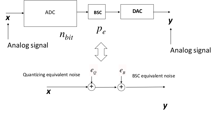
A PCM system can be represented by the cascade of an Analog-to-Digital
converter (ADC), Binary symmetric channel (BSC), and a Digital-to-Analog
converter (DAC) as shown in Figure. The ADC takes an analog signal and converts
to a digital one and the DAC does the opposite. The BSC models the
transmission of the bits representing the analog signal over a channel
which has a certain transition probability
-
What are the characteristics parameters of the PCM system?
-
Based on what final aim we decide the system parameters?
-
In fig what is the meaning of
$e_Q$ and$e_{BSC}$ ? -
What is the quality metric to assess a good reconstruction of the analog signal?
-
Define the class ADC with an attribute n_bit which stands for the number of bit of the ADC. Define similarly a class BSC which models the binary symmetric channel with a unique attribute error_probability which stands for the error probability
$P_e$ of the BSC in case of uniform distribution between 0s and 1s. Set the attributes in the constructor of the class. In both classes write a method or property snr() which calculates, respectively, the quantization SNR and the SNR of the BSC.In the exercise_1() function, plot, in dB, the quantization SNR for ADC n_bit = [2, 3, 4, 6, 8, 10, 12, 14, 16] and the BSC SNR for error probability
$P_e$ between 1e-12 and 1.Hint: you can write the SNR methods to accept both single or multiple values using numpy arrays. When creating the numpy array use the dtype parameter to int64 to avoid number representation overflow (see numpy documentation). Plot the SNRs on the y-axis and n_bit and
$P_e$ on the x-axis. For$P_e$ , set the x-axis in logarithmic scale (use plt.xscale("log")). -
Define a class PCM which models the the PCM system block diagram of Fig.1{reference-type="ref" reference="fig:my_label"}. The PCM class attributes are:
-
analog_bandwidth: a float number representing the analog signal bandwidth (in Hz) to be digitized, transmitted and reconstructed. Set it to an arbitrary value for the moment.
-
adc: an ADC class object, whose number of bits is provided as constructor input argument.
-
bsc: a BSC class object, whose error probability is provided as constructor input argument.
We neglect the DAC as we consider perfect analog signal reconstruction.
Write a method snr() of the PCM system class which computes the overall SNR due to the cascade of ADC and BSC.
Write a method critical_pe() of the PCM system class which computes the critical error probability
$P_{th}$ .Consider the possible number of bits array n_bit = [2, 4, 8, 16] and the error probability
$P_e$ between 1e-12 and 1. For each number of bit configuration , plot in the same figure the overall SNR (y-axis) vs the$P_e$ (x-axis, logarithmic scale). For each n_bit configuration, add an horizontal line of the quantization SNR and a vertical line of the critical error probability$P_{th}$ .Hint: Use different line colors to distinguish between the different n_bit cases. You can use the pyplot functions plt.axhline() and plt.axvline() to plot constant horizontal and vertical lines. Although we have seen a closed formula for the overall PCM system SNR, remember that it can be calculated as the parallel (in linear units) of the quantization and BSC SNRs:
$$SNR_{TOT} = \left( \frac{1}{SNR_Q} + \frac{1}{SNR_{BSC}} \right)^{-1}$$ -
-
Consider now an analog signal whose bandwidth is of 22 KHz. After the ideal reconstruction at the DAC output we want to obtain a quantization SNR of at least 80 dB. The digitized signal after the ADC is transmitted through a BSC whose error probability is
$P_e = 3.8e-7$ .